Electrical Safety Test
Description
The propose system will be composed of:
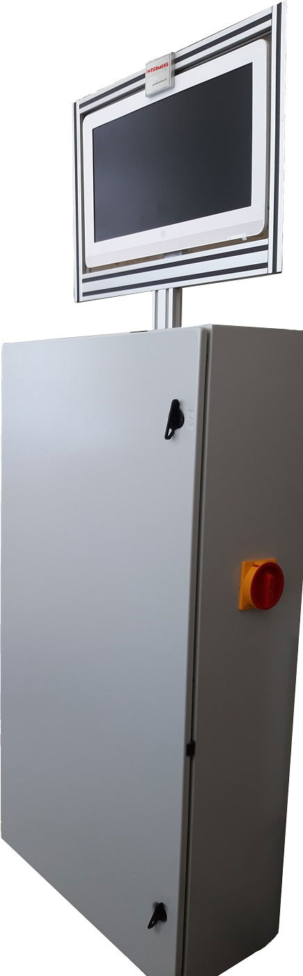
- Electrical Safety Testing And Functional testing station for manual or automatic connection
- Hardware accessories, software and documentation
- Key turn operation, installation and services.
The system is based on the following main requirements:
All the measures must comply with standard EN/IEC 60335-1 et IEN/IEC 60335-2-31 :
· Frequency of 50 Hz.
· Voltages single phase from 230Vac (without regulation).
· 0W to 11Kw (50 Ampere) power measurement.
· Control Panel with control by operator for test high voltage, validation and cancellation,
· Red Or Green light shown on the Screen
· Management of the devices checked by scanner is optional
· Labeling is optional
Electrical protection of the post by an “Emergency stop” button.
Specification
1.1.1 Hipot AC
Electric insulation test applied with High Voltage supply among the short circuited live parts on product's power-plugs and the earth wire
Characteristics
· Output power: 500 VA
· Current: 0 – 100 mA
· Accuracy: 1,5% F.S.
· Test type: class I (earth conductor included)
Test Parameters
· Measure range: 0 – 100,00 mA
· Test voltage: 100 – 1250 Vac
· Test time: 0,5 – 10,0 s
1.1.2 Earth circuit resistance And Continuity Test
Checkout of the electric resistance given by the earth circuit at the alternating current direction. Test execute with equipped transformer power supply.
Characteristics
· Test voltage: 12 Vac without load
· Test method: 1 crocodile cable on body and power plug.
· Accuracy: 3% F.S.
Test Parameters
· Measure range: 0 – 1000,0 mOhm
· Test current: 25A supplied by transformer
· Test time: 0,5 – 10,0 s
1.1.3 Leakage current
Checkout of the leakage current in the earth conductor when the tested device is supplied at the nominal voltage (nominal V) .
Characteristics
· Accuracy: 1,5% F.S.
Test Parameters
· Measure range: 0 – 10,00 mA
· Test voltage: Nominal Voltage
· Test type: Measure the leakage current which flows on phase or neutral line.
· Test time: 0,5 – 10,0 s
1.1.4 Functional test – Current and power measure
Functional verification and measurement of electrical voltage test set in the head of the program. The voltage must be applied to the DUT is taken directly from isolation transformer 12.000VA with or without regulation.
The measure must be into the range for all test time.
Caratteristics
· Error: 1,5 % F.S. (for current)
· Error: 3 % F.S. (for power)
Parameters
· Measure range: 0 – 50,00 A or 0 – 11000 W
· Settling time: 0 – 600,0 s
· Test time: 0 – 600,0 s
· Power off end of test: Yes
1.1.5 Current and power in synchronism
The tests are intended to synchronize the absorption measurements with an event (action of an operator) that during the test phase varies some test conditions. Is a classic application of electric cookers, each knob position is linked to a different value of power consumption. The test time is fixed and the synchrony between the operator and the tester is facilitated by an acoustic signal when the measure has been successful and the instrument is waiting for a new variation. The tests are divided between current measures and measures in watts.
Parameters
· Measure range: 0 – 50,00 A or 0 – 11000 W
· Reference threshold: 0 – 50,00 A or 0 – 11000 W
· Settling time: 0 – 600,0 s
· Max time: 0 – 600,0 s
· Power at and of test: Yes / No
1.1.6 Auto Mode / Manuel Steps Mode
The test goes on automatically from start till end of the test in Auto Mod. In the case of safety fail occurring it stops and pause the test.
In Manuel step mode the operator can control whole the steps himself as step by step.
1.1.7 Thermal printer (Optional)
Will be provided the customer with a thermal printer panel, connected at the serial port usb.
Continuous form paper, width paper 58mm, 40 Characters / line
1.1.8 PC Interface
Will be made available to the user friend software on PC and Microcontroller.